Sunday, July 22, 2012

BMS install

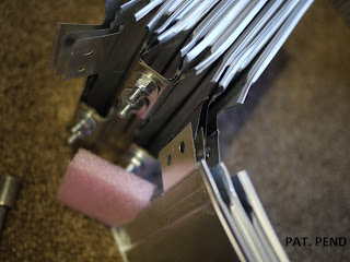
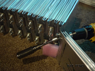
I got all the BMS mid boards installed today. The Lithiumate Lite is about as simple a system to install as possible (short of not having a BMS :).

Some of the things I like about it so far is the board to board connection is realatively easy and the diagnostic light on the PCB that blinks 6 times to let you know you installed it correctly and that it is working. The boards are pretty small and fit well with 3 cells in parallel. Part of the way through I realized if I installed half of the boards upside down this gave you a bit of extra clearance.


Notice I said upside down, NOT BACKWARDS! This brings me to one of the things I don't like on the system. If you install a cell backwards (i.e. wrong polarity) it is dead. Even for a millisecond. Elithion is very clear about this in their literature but it just seems like a diode to protect the boards would have been a easy fix. So with that in mind, I made sure I had a little installation procedure and followed it. Elithion manual seems very good along with some videos (with no audio for some reason) but for my application I set the pack on it's side and did half where the PCB would hang down to gravity. I was anal and checked every connection with the DMM first then verfied the LED blinked before tightening the nuts down.


I did one full side then flipped the module and did the mid boards in the other direction.


Cut then stripped all of the wires to the right length.


I then made the connections, again one side at a time.


This just helped to get in a pattern and ensure no mistakes.


Just to reiterate what I said about the BMS earlier. If I had cells that I was 100% confident in then I would not have bothered. But being this is an experimental pack design I am far from it (not even close to 3 sigma :). So I decided I needed to montior each cell. I looked into Battery Monitoring Systems and wasn't impressed. I found the Elithion system gave this functionality along with a management system for a very reasonable price and had a lot more features. I must say for someone that is but skeptical of BMS, I am pretty impressed with the system so far. But I am not done yet either... :)

I am also looking if I can use the lithiumlite system just for monitoring and keep my pack bottom balanced.

BTW, Before I purchased I also found all the fabrication was done here in Colorado (Broomfield, CO). I am a big fan of buying locally so this was icing on the cake for what I already thought was the best system and best value.

I also bought a set of KYB struts with springs for only $150. I will hold off installing them till later:


Saturday, July 21, 2012

Mark II module

The original module design has undergone another change to improve the end plates. I went back to a previous design that uses nice thick 3/8" aluminium plates. I had originally try to keep things as DIY friendly as possible so I used .120" sheet and the L angles. The problems is the sheet is not stiff enough and doesn't do a very good job of distributing the force over the whole face of the cell and I worry if could lead to premature cell failure. Going to 3 channels makes it better but still not as good as I would like So I am getting quotes on having the plates CNC'd.


I hope to have the parts in a week or two and will update from there. If anyone else is interested in getting in on my CNC order let me know.


In the mean time I am installing my BMS and should have pics of that tomorrow.

Wednesday, July 18, 2012

Charge!

Since I have battery packs now I need a way to charge them. So I got the charger mounted tonight:


I chose this location because I wanted the weight up front to help with weight distribution. It is also next to the battery terminals at the charger making the cable run short. I also wanted to place it on the passenger side to offset some of my weight as I will be driving it to work sans passenger most of the times.


I went with the Manzanita Micro PFC20. I could have gone with the cheaper Chinese made Elcon but I wanted a made in the USA quality unit and the capability of adjusting the current draw on the fly. We have seen great improvements in controllers (i.e. Evnetics) but this charger really seems right out of the 90's. For my relatively small pack 20amp max is plenty though if I got that PFC60 I could recharge from my morning commute in less then 30 minutes. :) I have something special in mind for the charge port but more on that later....

Saturday, July 14, 2012

Summary of A123 module design

I have documenting my miata build in the "All Conversions and Builds" section and on my blog at:

http://electricmiata.blogspot.com/

I thought my pack build up might be worth a summary for others to build.


I went through at least a dozen design iterations and each time tried to simplify it and make it as DIY friendly as possible.  I think the result is a pack that is about as light as you could possibly make it and you can still run max power without any additional life or performance hit.  For my car I will only be driving in nice weather so cell cooling was my only concern.  But it you wanted to put it in a insulated enclosure you could also heat the cells by circulating warm air.

The basic design end up being really just a DIY version of the A123 modules. 


The cells are stacked together with cooling fin sandwiched between every other cells.  They are restrained by end places made of .120" aluminum sheet and 1" aluminum angle.  The assembly is clamped together by 1/4" steel all thread.

For the electrical connections the tabs were bent and sandwiched together with 3 cells connected in parallel. 

I punch holes in the cells using a simple block I made that fit into a 3 hole punch.


The holes went very quickly but unfortunately removing the glue from the barcode stickers did not.  You might have been able to leave it but adhesive is typically very non-conductive.  To reduce the current density at the connections I interleaved the tabs. 


The pack was a little harder to assemble but the result was three times as much surface area for the current to flow through. The hardware was just zinc plated 1/4 bolts, washers and locking nuts. 


The BMS will connect to the extra threads on top of the nuts.

DIY A123 modules ready to go

Now that I am back stateside I took the afternoon to build the final version of my modules.


 I made up some quick templates to crank out new cooling fins that look a lot more professional then Rev 0.


...I also made up new end plates and end bars...


...and replaced the end cables with .25" all thread...

 So in short I remade everything but the cells from before. :)  The result is a module design that I am finally happy with and can easily made with pretty basic hand tools cheap and quickly.  I'd say once the cells were ready (tested, destickered and 2 hole punched) I took me about 4-8 hours to assemble 250 cells into modules.

I dry fit the modules in the back of the Miata so I can start on the mounting brackets.


3 modules get installed here where the fuel tank used to be and a 4th one get's installed up front where the radiator used to hang.

Next up is the mounting brackets for the modules and installing the BMS.  Assuming I don't have to suddenly  leave the continent for work again those items shouldn't take too long.

Thursday, July 5, 2012

Now I have power!

Well I finally got a few hours to assemble my 250 A123 cells into modules.  Once I got the system down it went pretty quickly.  I have the cells assembled into 4 modules.  3 identical ones made of 3p18s that will go behind the seats where the gas tank used to go.  The other cells get mounted in a single module of 3p29s that goes up front where the radiator used to be.  I went back and forth on how I was assembling the modules but the final design just uses bolts nuts and washers do make it very DIY friendly.  If people are interested I can post specific details on the tab connections.  


Once I had all the tab connections I needed a way to mount them.  I made up some quick end plates with some L brackets so I can connect cables to clamp them together.


For cables I actually had a bunch of left over flight control cables.  I simply cut them down and spliced them together.  I originally going to use some eye bolts but happened to have these cables. 


I also cut up some  .008 aluminum into 8" squares to act as cooling fins.  I slid them in between every other cell. 

 This greatly increases the heat transfer from the cells.  Individually the cells will be just fine but when you stack them together you decrease the cooling surface area by several orders of magnitude.  To solve this aluminum uses the large surface area from the sides and conducts the heat away to the fins.  The fins stick out 1" from either end of the cell for convection to wick the heat away.  Keeping the cells cool is critical to maintain cell life.  This is a fair weather car so I won't be driving it in the cold but this also could be used for heating if you needed.


This pack still needs some adjustment but I wanted to get it made before I left town for a few weeks.