Monday, December 24, 2012

Stage 1 complete!

Well today we got the Miata titled as a EV and plated!  The first stage of this project was to to convert the car to a street legal EV and that is now complete.  As with all projects like this there are little things that will be done (like the brake lights stopped working) but getting it titled and registered is a big step.


Look ma, no exhaust!

For people registering a EV conversion is Colorado it is actually very easy, depending on who you ask.  :)  Do not take it to a emission center.  They will tell you that you need to get a bunch of extra paperwork and inspections as if it were a kit car.  Don't go down this road (pun intended).  Instead call your local motor vehicle registration. All you really need is a VIN inspection which is easy and cheap ($8).


We talked to the nice people (no sarcasm intended) at the Douglas County MVR and they told us that Douglas county even does onsite inspections!  We called the number they gave us and sure enough an hour later a officer showed up and did the VIN inspection in my garage!  For the conversion all the officer does is puts on the form that it is a title correction.  He does the VIN check like normal but he just puts a E in for fuel type.  Take that down the MVR and you get your plates a EV title will be mailed to you.

What's next?  Well I am trying to decide on if I will do stage 2 and go dual motor with direct drive.  I have a Brand new Transwarp9 on the bench ready to go but I don't know that I have the battery pack to make it worth while.  My options would be but more A123 cells to pump the voltage from 184VDC to 307VDC or redo the whole pack in some CALB CA70's.  Neither of which are particularly appealing. In the mean time I will be upgrading the suspension, adding a roll bar doing some body work this winter too.


I set a goal for myself to do one conversion a year.  I think my conversion for 2012 will be a plug in hybrid.
I have a 2005 GMC Canyon Crew Cab 4x4 with the 4 cylinder with the a 5 speed manual transmission which I am going to be adding a 108V LiFePO4 pack a Curtis 550amp controller and a AC24LS motor.

This winter I will be experimenting with AC using the AC24LS motors which I am documenting on another blog:

http://evengineering.blogspot.com/

Merry Christmas!

Saturday, November 24, 2012

How to make a cool charge cap for $60


I wanted to share the charge port I put on my Miata.  Most conversion use the place for the gas filler.  


While this works well I didn't want that for my conversion because I wanted to have my charge port to be mounted up front instead of the back.  I wanted this for a couple reasons:


1st: is because I was mounting my charger up front and didn't want to run the 220V wiring from back to front

2nd: I wanted the charge port in my line of sight to prevent the possibility of driving away while plugged in (there are electronic safeties too)

3rd: This is just cooler

The standard NEMA L14-30 works fine but will collect debris, water, snow, etc and leaves a lot do be desire aesthetically. 


So I looked for a housing that would protect the connector and dress it up.  After much searching for caps that were either too small or too expensive.  Then I came across 1967-68 Barracuda 1967 GTX 1968 Charger Flip Top Fuel Cap.  I picked a used one up for $40 that was in great shape but new reproductions run around $100.  You can also get one for the charger which should work too (I don't care for the looks

When I got the cap I was pleasantly surprised to find that the outlet fit perfectly inside the cap!


I only had to do a little trimming for the hinge and drilled one hole in the plug housing and it was ready to install. 


I potted the plug into the cap with some black silicone to make it weather tight and make a cleaner looking install.  The nice spring loaded rubber seal that the cap has to keep the gas in does a great job of keeping moisture out.  So for $60 I had a cool looking cap.


I had mounted in the hood I need to make provisions for the hood moving so a spring was added to keep it from binding.

Tuesday, November 20, 2012

2 month inspection of A123 cells


I wanted to give a update on my A123 module after a few months.  There is good news and bad news.  The bad news is that I have more bad cells, the good news is that there is a pattern to the failures.  I have 4 modules in my car, 3 are the original Mark 1 design and the 4th is the Mark II with the much stiffer endplates.  I did a pretty detailed inspection of all the cells.  The pattern to the failures is cell pressure, either too much in the case of module 2 or uneven pressure at the thin end plates for all of the early Mark I designs.


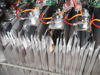
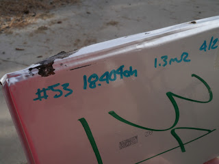
Module 1, Mark I, RevA: 1 cell had signs of electrolyte leakage and 1 other cell had a little spot that looks like mold.

This spot is the start of corrosion in the pouch.  The two cells were right next to the end plates.  I am upgrading it to Rev B.

Module 2, Mark I, RevA: Numerous cells had signs of electrolyte leakage.  Most of them were on the ends but some in the middle of the pack.  This pack was also problematic last time I inspected it.  My guess is that I over compressed the cells the first time I built it that caused undetectable damage. The second time I assembled it there was much less clamping force but I think the damage was already done.  I am putting this pack aside for now until I have a had a chance to evaluate it further.


Here you can see several cells failed from the pack.  In some the electrolyte is still trapped between the clear outer film and the silver inner layer.


Module 3, Mark I, RevA: 1 cell had signs of electrolyte leakage on one side.  This cell was locate right next to the negative end plates.  Failure looks like it was due to uneven pressure on the cell.  I am upgrading it to Rev B.


Module 4, Mark II, RevB:  I actually had a leaking cell for the first time on the Mark II module.  I didn't discover it until I checked each one separately.  The cause was quite apparent, user error.


When I had installed one of the cooling fins the sharp thin aluminum cut and tore the thin pouch material.  I cannot over emphasize how gentle you need to be with these pouch cells.  This is probably my biggest issue with using these cells. So I replaced the bad cell and also added electrical isolation using transparancies.  I only did half of the pack.  This way I will see the effect, if any.  I also upgraded it to Rev B too.


As with all my other posted I wanted to post what I have found with testing so far.  Hopefully it will save others some headaches if they decide to use the pouch cells, (or in some cases it might convince them it's too much work :-)  I expected using these cells to be a learning experience, but this has been more work expected.  I have spent more time and effort on the batteries then I have on the rest of the conversion but that is part of the fun of the project.  :)

The fallen cells


Sunday, September 30, 2012

Rev A and on to Rev B

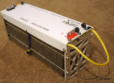
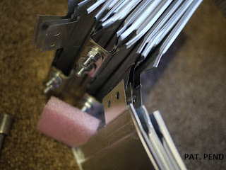
Here are some pictures of the Mark II pack.


I have been having problems with one of my Mark I pack having leaking cells and I think it is due to uneven pressure on the cells.


I pulled the pack and you can see the electrolyte on the cooling fin


I am glad I made the pack easy to remove and replace cells.  This is the third time I have had to R+R bad pouches.


The MkII has very stiff end plates which I think mitigates this problem.  A couple of changes from the Rev - and Rev A design:  I glued plastic plates over the inside of the end plate to prevent possible shorts to the end plates from the tabs.  I also put a sheet of elastic foam between the end plates and the outer most cells.  This foam sheet acts as as spring to control the pressure on the cells due temperature, cycling, etc. and insultation on the threaded rod to prevent a electrical pat from the fins that may be touching the rods.

I am considering adding insulation in between the cells.  I haven't had a problem with it but others have:

http://www.diyelectriccar.com/forums/showthread.php/a123s-gone-bad-78971.html

The factory modules don't have any intracell insulation but obvious some people are having problems.  I have to do some more head sratching as to what the root cause of the problem is first.

Friday, September 21, 2012

Keeping cool


Still not home yet but a couple hour layover is as good as time as any to update the blog.  I have had a few people ask me about the cooling fins on the pack so I am posting so more info.  

I know there is much debate whether thermal management is required for these batteries.  Some say it is not required while others say it is essential for battery life.   In reality they are both correct.   If you are taking a leisurely cruise on a spring day then thermal management will not be a problem for you.  The starting temperature of the pack and the low discharge rates don’t require it.  However if you are driving in more extreme conditions or operating your batteries at a high discharge level then thermal management becomes much more important.  For instance if you are doing laps +20 on a track on a hot summer day then your batteries will NEED cooling, not to mention every other system on your car:


The coolings fins placed between the cells are essential for getting the heat out of the cells.  The fins are made from 8” wide aluminum flashing from Lowes.  It comes in 25’ long rolls that are cut into squares.  Since I don’t like making the same part more than once, I set-up a quick line to crank out a hindered in a matter of minutes using a $30 paper cutter from the office supply store.


The cutter comes with a simple fence and has no problems cutting the soft thin aluminum.

As you can see in the picture I setup the cutter and roll on a bench so I simply unroll it cut and repeat. 
For this pack I used one fin every other cell.  This assures that each cell is in direct contact with a fin and should be minimum if your application requires cooling.  Fewer fins will only cool some cells and result in potentially significant variations in cell temperatures.  For very high power and ambient temperatures you can step up to a fin in between every cell for double the cooling.  I used bare aluminum flashing for maximum heat transfer and it was the only finish I could find in 8” width.  The flashing is also available in prepainted which could provides a thin barrier which could help with voltage leakage from the pouch casing but will decrease the effectiveness of the fin some amount.  Whichever flashing you use make sure that the surface of the flashing and the cells are clean before assembly.  Any dirt or debris that becomes trapped can potentially damage the cell during assembly and/or result in wear over time.

Thursday, September 6, 2012

Quick update: The car runs.

Sorry for the long time between post but between work and summer time in Colorado I haven't had much free time to update my build log.  The short story is the car is running now but still tying up loose ends.   Battery packs are all built and installed, 2/0 cable is in with big manual disconnect, DC/DC converter is in and the vacuum for the brakes.  


Really all that is left is some small wiring tasks. I haven't done any real road testing yet as I am finishing the BMS install and more importantly I need to wire a 30amp 220V plug in my garage so I can actually charge up my cells.


I was hoping to have the car finished up this week as I am off to work on the other side of the globe for a few weeks.  So I will probably get the car done in October just in time for the weather to get cold. :)

Sunday, July 22, 2012

BMS install

I got all the BMS mid boards installed today. The Lithiumate Lite is about as simple a system to install as possible (short of not having a BMS :).

Some of the things I like about it so far is the board to board connection is realatively easy and the diagnostic light on the PCB that blinks 6 times to let you know you installed it correctly and that it is working. The boards are pretty small and fit well with 3 cells in parallel. Part of the way through I realized if I installed half of the boards upside down this gave you a bit of extra clearance.


Notice I said upside down, NOT BACKWARDS! This brings me to one of the things I don't like on the system. If you install a cell backwards (i.e. wrong polarity) it is dead. Even for a millisecond. Elithion is very clear about this in their literature but it just seems like a diode to protect the boards would have been a easy fix. So with that in mind, I made sure I had a little installation procedure and followed it. Elithion manual seems very good along with some videos (with no audio for some reason) but for my application I set the pack on it's side and did half where the PCB would hang down to gravity. I was anal and checked every connection with the DMM first then verfied the LED blinked before tightening the nuts down.


I did one full side then flipped the module and did the mid boards in the other direction.


Cut then stripped all of the wires to the right length.


I then made the connections, again one side at a time.


This just helped to get in a pattern and ensure no mistakes.


Just to reiterate what I said about the BMS earlier. If I had cells that I was 100% confident in then I would not have bothered. But being this is an experimental pack design I am far from it (not even close to 3 sigma :). So I decided I needed to montior each cell. I looked into Battery Monitoring Systems and wasn't impressed. I found the Elithion system gave this functionality along with a management system for a very reasonable price and had a lot more features. I must say for someone that is but skeptical of BMS, I am pretty impressed with the system so far. But I am not done yet either... :)

I am also looking if I can use the lithiumlite system just for monitoring and keep my pack bottom balanced.

BTW, Before I purchased I also found all the fabrication was done here in Colorado (Broomfield, CO). I am a big fan of buying locally so this was icing on the cake for what I already thought was the best system and best value.

I also bought a set of KYB struts with springs for only $150. I will hold off installing them till later:


Saturday, July 21, 2012

Mark II module

The original module design has undergone another change to improve the end plates. I went back to a previous design that uses nice thick 3/8" aluminium plates. I had originally try to keep things as DIY friendly as possible so I used .120" sheet and the L angles. The problems is the sheet is not stiff enough and doesn't do a very good job of distributing the force over the whole face of the cell and I worry if could lead to premature cell failure. Going to 3 channels makes it better but still not as good as I would like So I am getting quotes on having the plates CNC'd.


I hope to have the parts in a week or two and will update from there. If anyone else is interested in getting in on my CNC order let me know.


In the mean time I am installing my BMS and should have pics of that tomorrow.

Wednesday, July 18, 2012

Charge!

Since I have battery packs now I need a way to charge them. So I got the charger mounted tonight:


I chose this location because I wanted the weight up front to help with weight distribution. It is also next to the battery terminals at the charger making the cable run short. I also wanted to place it on the passenger side to offset some of my weight as I will be driving it to work sans passenger most of the times.


I went with the Manzanita Micro PFC20. I could have gone with the cheaper Chinese made Elcon but I wanted a made in the USA quality unit and the capability of adjusting the current draw on the fly. We have seen great improvements in controllers (i.e. Evnetics) but this charger really seems right out of the 90's. For my relatively small pack 20amp max is plenty though if I got that PFC60 I could recharge from my morning commute in less then 30 minutes. :) I have something special in mind for the charge port but more on that later....

Saturday, July 14, 2012

Summary of A123 module design

I have documenting my miata build in the "All Conversions and Builds" section and on my blog at:

http://electricmiata.blogspot.com/

I thought my pack build up might be worth a summary for others to build.


I went through at least a dozen design iterations and each time tried to simplify it and make it as DIY friendly as possible.  I think the result is a pack that is about as light as you could possibly make it and you can still run max power without any additional life or performance hit.  For my car I will only be driving in nice weather so cell cooling was my only concern.  But it you wanted to put it in a insulated enclosure you could also heat the cells by circulating warm air.

The basic design end up being really just a DIY version of the A123 modules. 


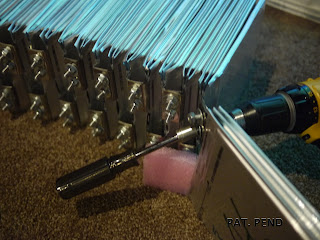
The cells are stacked together with cooling fin sandwiched between every other cells.  They are restrained by end places made of .120" aluminum sheet and 1" aluminum angle.  The assembly is clamped together by 1/4" steel all thread.

For the electrical connections the tabs were bent and sandwiched together with 3 cells connected in parallel. 

I punch holes in the cells using a simple block I made that fit into a 3 hole punch.


The holes went very quickly but unfortunately removing the glue from the barcode stickers did not.  You might have been able to leave it but adhesive is typically very non-conductive.  To reduce the current density at the connections I interleaved the tabs. 


The pack was a little harder to assemble but the result was three times as much surface area for the current to flow through. The hardware was just zinc plated 1/4 bolts, washers and locking nuts. 


The BMS will connect to the extra threads on top of the nuts.