http://electricmiata.blogspot.com/
I thought my pack build up might be worth a summary for others to build.
I went through at least a dozen design iterations and each time tried to simplify it and make it as DIY friendly as possible. I think the result is a pack that is about as light as you could possibly make it and you can still run max power without any additional life or performance hit. For my car I will only be driving in nice weather so cell cooling was my only concern. But it you wanted to put it in a insulated enclosure you could also heat the cells by circulating warm air.
The basic design end up being really just a DIY version of the A123 modules.
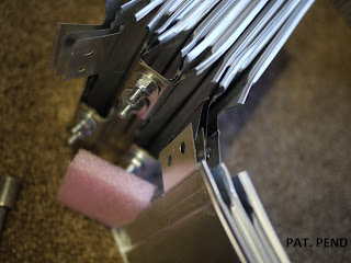
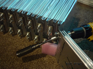
The cells are stacked together with cooling fin sandwiched between every other cells. They are restrained by end places made of .120" aluminum sheet and 1" aluminum angle. The assembly is clamped together by 1/4" steel all thread.
For the electrical connections the tabs were bent and sandwiched together with 3 cells connected in parallel.
I punch holes in the cells using a simple block I made that fit into a 3 hole punch.
The holes went very quickly but unfortunately removing the glue from the barcode stickers did not. You might have been able to leave it but adhesive is typically very non-conductive. To reduce the current density at the connections I interleaved the tabs.
The pack was a little harder to assemble but the result was three times as much surface area for the current to flow through. The hardware was just zinc plated 1/4 bolts, washers and locking nuts.
The BMS will connect to the extra threads on top of the nuts.


No comments:
Post a Comment